
Transmission Structure Types: A Visual Field Guide for Utility Drone Inspection
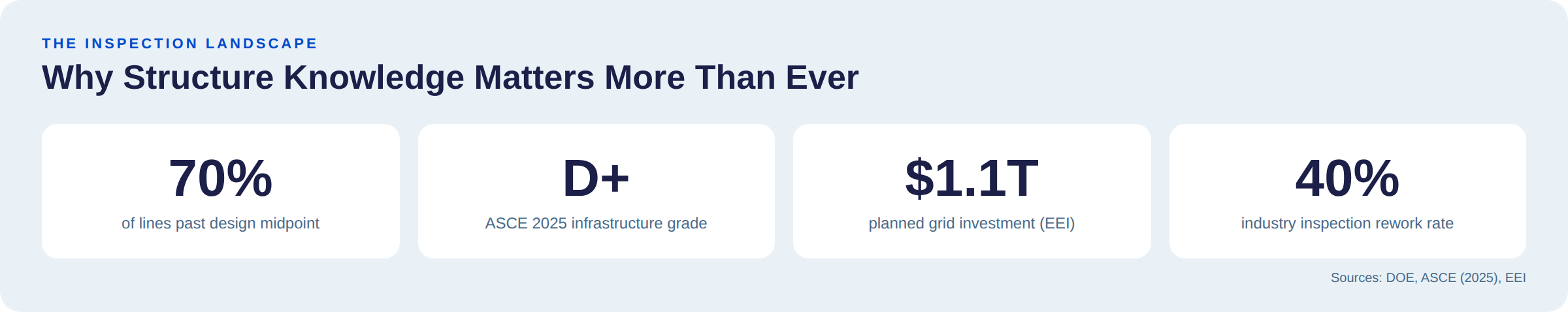
70% of NAM's transmission lines were built before most of today's drone pilots were born.
The Department of Energy puts it plainly: the grid's towers, conductors, and hardware mostly date to the 1960s and '70s. The ASCE's 2025 Report Card dropped U.S. energy infrastructure to a D+. EEI members have committed $1.1 trillion in grid investment over the next five years.
More aging structures means more inspection work than at any point in history. One operator recently audited 618 lattice towers in nine days with warranty-ready documentation, delivered before winter freeze-up. That's the pace the industry is moving toward.
Most experienced DSPs know their way around a transmission corridor. They understand flight safety, camera settings, and how to work around energized assets. But the utility inspection market is getting more demanding: not because pilots aren't skilled, but because what counts as a complete deliverable keeps expanding.
Utilities used to accept structure-level imagery. Now they want component-level condition data — every insulator disk, every cotter key, every strain connection — captured at angles specific to the structure type being inspected. A dead-end tower has different critical hardware than a tangent. An H-frame ages differently than a monopole. A 765kV lattice tower requires a fundamentally different flight plan than a 69kV wood pole.
When that structure-specific knowledge isn't baked into the capture, data gets rejected. Across the industry, rework rates on utility inspection contracts still run as high as 40%, often due to the inspection scope not matched to the infrastructure.
Whether you're onboarding new pilots or standardizing capture across a growing roster, the goal is the same: structure-specific knowledge that translates directly to utility-grade deliverables. So, here's what every pilot should know before they fly.
From the Detect Data Quality Program curriculum. Covers structure identification, component anatomy, and the field knowledge that turns a drone operator into an infrastructure inspector.
Voltage Class Dictates Your Entire Inspection Plan
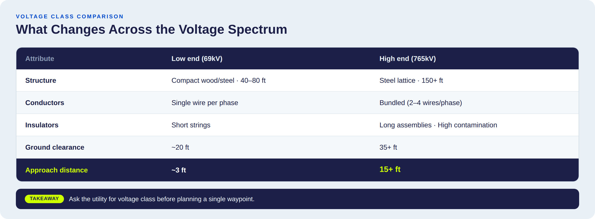
Skip the textbook definition of transmission lines. Here's what actually matters at 400 feet:
The voltage rating of the line you're inspecting determines the structure height, conductor spacing, insulator length, right-of-way width, and your minimum safe approach distance.
A 69kV H-frame and a 765kV lattice tower aren't different sizes of the same thing. They're fundamentally different inspection targets — different flight plans, different components, different failure modes.
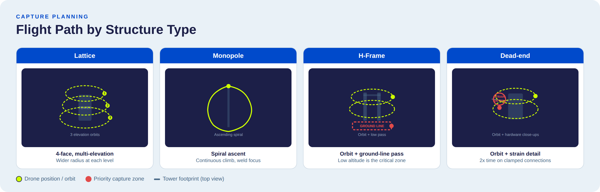
The Four Transmission Tower Designs
Every guide ranking for "types of transmission towers" classifies them by engineering spec. That's useful if you're buying steel. Here's the version that matters when you're flying.
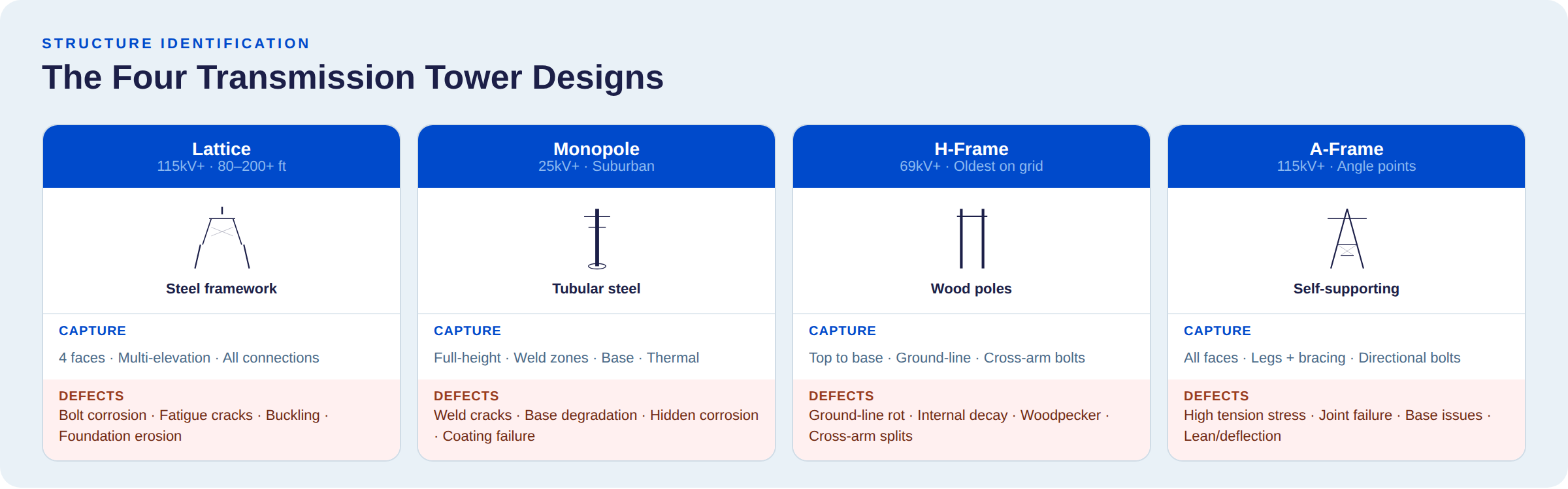
Lattice Towers
Steel framework structures. Galvanized angle-iron, bolted together on-site. The most common electrical tower for high-voltage transmission (115kV+). Typically 80-200+ feet.
The inspection challenge: Complex geometry means dozens of potential defect locations — connection points, gusset plates, base plates, cross-arm attachments. Corrosion hides at bolted joints. Fatigue cracking starts where you can't see it from one angle.
What the utility needs from you:
- Multiple elevation passes (not one orbit at one altitude)
- All four faces of the structure
- Close-range shots of cross-arm connections, base plates, anchor bolts
- Foundation condition at ground level
Case in point: DetectOS caught a loose clevis bolt on a brand-new HVDC lattice tower that traditional QA missed completely. A few more threads of engagement lost, and that bolt drops an HVDC conductor — $1M+ outage, week-long unplanned shutdown.
Monopoles
Single tubular steel or concrete poles. Gaining ground in suburban corridors for lines at 25kV+.
The inspection challenge: The uniform surface makes pilots complacent. The defects that matter aren't obvious:
- Weld seam cracking (especially circumferential welds)
- Hand hole / access panel corrosion
- Base-to-foundation connection degradation
- Coating failure hiding surface corrosion underneath
What the utility needs from you: Full-height documentation. Weld zones. Base connections. Hardware attachments at the top. Thermal imaging is increasingly requested for sub-surface corrosion.
H-Frames
Two vertical poles (usually wood) connected by a horizontal cross-arm. Common at 69kV+. A massive portion of the North American grid — and among the oldest structures still standing.
The inspection challenge: Wood lies to you. It can look solid from the air while being rotten inside. The defects that kill H-frames:
- Ground-line rot (the #1 failure mode — and you have to fly low to capture it)
- Internal decay invisible to RGB cameras
- Woodpecker damage
- Cross-arm splitting at through-bolt holes
The decay mechanics - and the groundline testing that catches them - are the same ones that govern the nation's 130 million wood utility poles; H-frames just fail at transmission scale.
What the utility needs from you: Both poles, top to base. Ground-line close-ups. Cross-arm connections — bolt condition, wood checking, splits.
Case in point: A regional utility struggled for a decade to get capital approved for two aging wooden transmission lines. Then they ran a one-day drone inspection of 96 H-frame structures through DetectOS. The executive committee saw the visual evidence. Multi-million-dollar rebuild approved in ten minutes.
A-Frames
Triangulated steel lattice. Self-supporting (no guy wires). Used at 115kV+ where the line changes direction or carries heavier mechanical loads.
The inspection challenge: A-frames show up at angle points — where conductor tension peaks and a structural failure would do the most damage. Higher mechanical stress means tighter inspection standards on every bolted connection.
What the utility needs from you: All faces documented. Legs, bracing, and every connection bearing directional load.
Structure Function Matters as Much as Structure Design
Knowing the shape (lattice, monopole, H-frame) is half the picture. The other half: what mechanical job is this structure doing on the line?
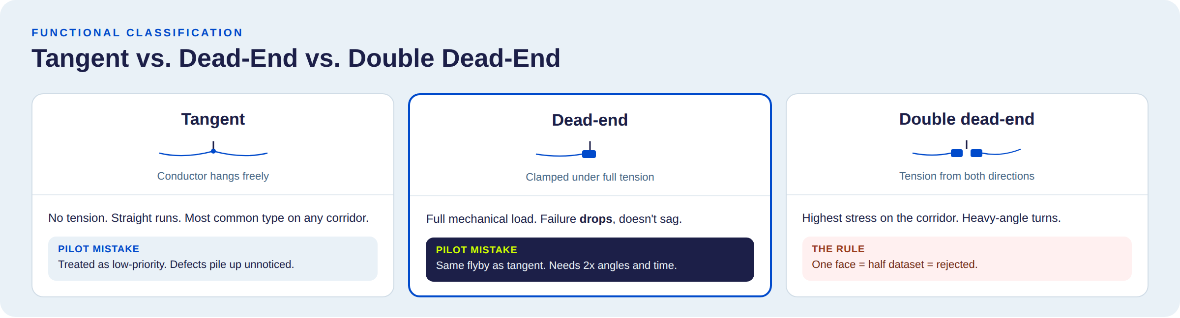
Tangent (Suspension)
The conductor hangs freely. No longitudinal tension. Straight-line runs. The most common structure on any corridor.
The mistake: Pilots treat these as low-priority. "It's just a tangent." Meanwhile, tangent structures quietly accumulate insulator contamination, bird nesting, and hardware corrosion between inspection cycles — specifically because nobody pays them enough attention.
Dead-End (Strain)
The conductor is clamped, not suspended. The structure absorbs the full mechanical tension of the line. Found at terminations, major angle points, and line section transitions.
The mistake: Giving dead-end hardware the same flyby treatment as tangent hardware. Every strain insulator, yoke plate, and clamped connection is under active load. A failure here doesn't sag — it drops. When transmission line failures cascade through the grid, dead-end hardware shows up disproportionately in root-cause analysis.
Dead-end structures need: More close-ups. More angles. More time. Budget for it.
Double Dead-End
Full tension from both directions. Heavy-angle turns.
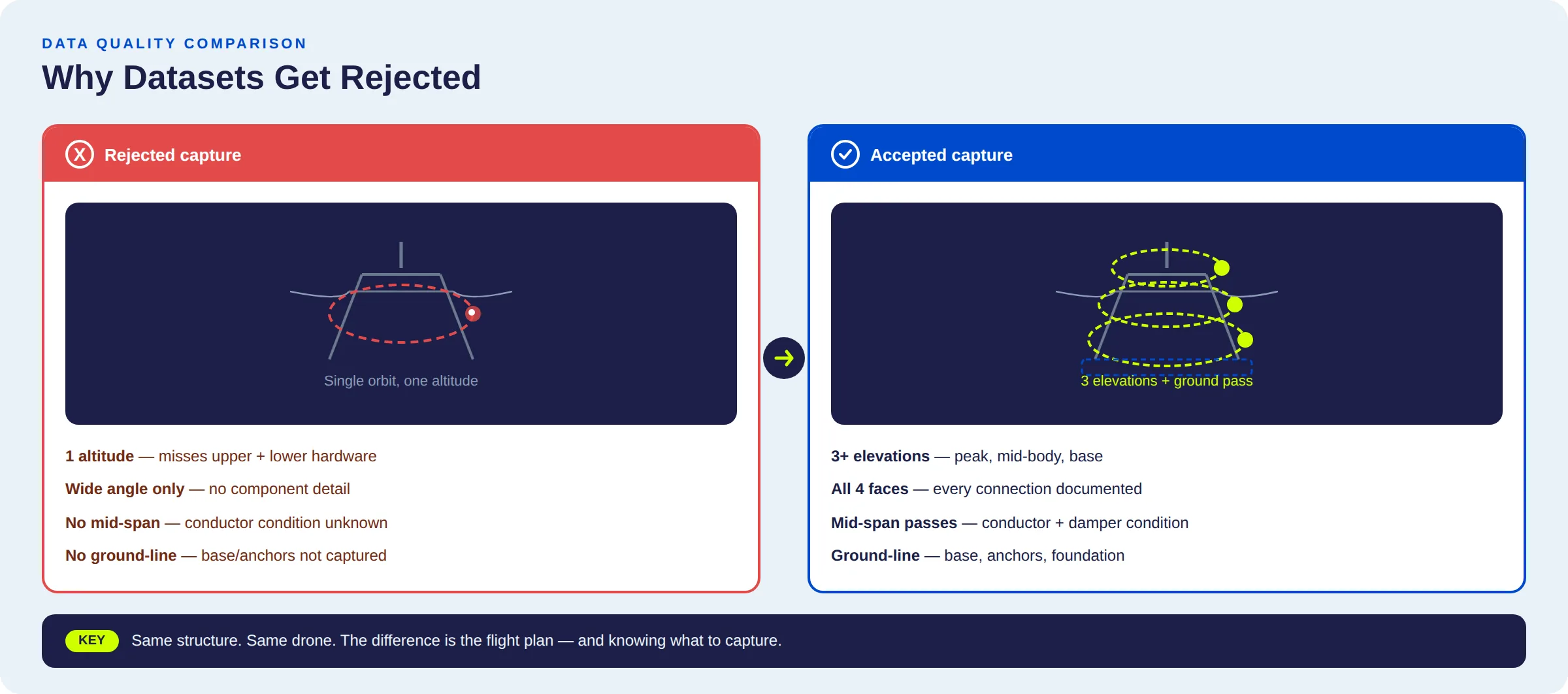
The rule is simple: If you only capture one face of a double dead-end, you've delivered half a dataset. The utility will reject it.
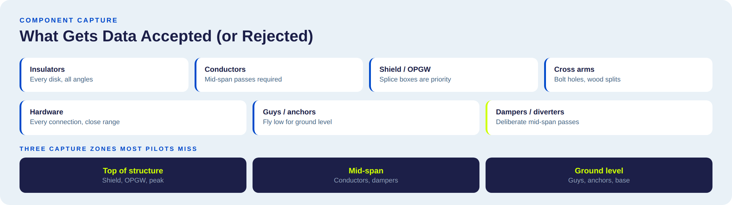
The Components That Get Your Data Rejected (Or Accepted)
Utilities don't reject datasets because the tower photo is bad. They reject them because the component photos are missing.
An asset manager isn't looking for an aerial portrait. They need documented evidence of specific component conditions. Miss those, and the whole mission gets reflown — on your dime if you're on a fixed-fee contract.
This is part of a broader shift: utilities are moving from calendar-based inspection to condition-based asset management. That shift demands better input data. The video above walks through each component with real inspection imagery.
Here's the quick-reference version.
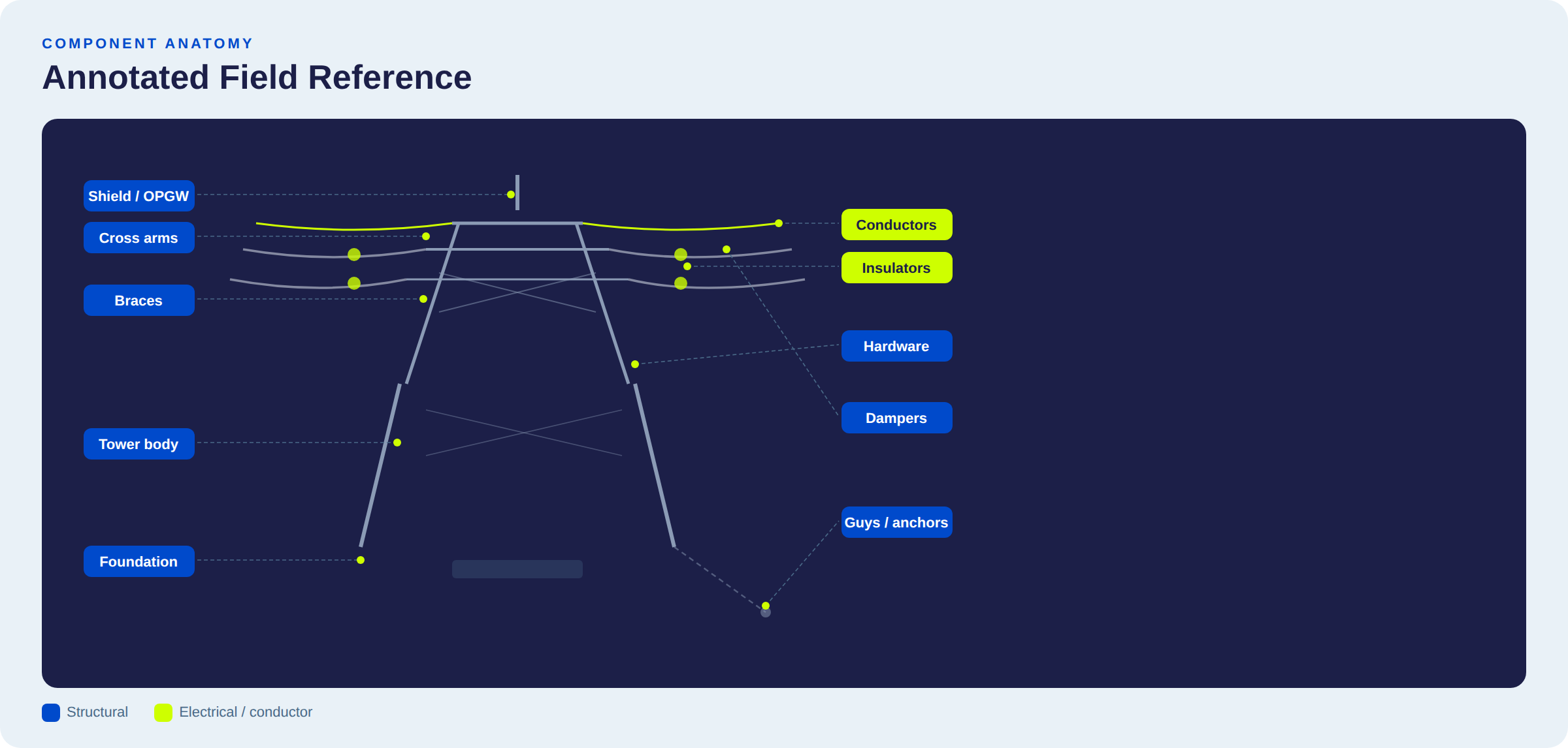
Insulators
What they do: Prevent electricity from tracking through the structure to ground. Glass, porcelain, or composite polymer, shaped like bells or disks.
What goes wrong: Cracks, chips, burn marks, surface contamination → flashover risk → outages, wildfires.
Capture requirements:
- Every bell/disk in the string, not just a wide shot of the assembly
- Angles that reveal surface condition and any chipping
- DetectOS flags insulator defects invisible at standard flight distance — the kind that only surface through structured, multi-angle capture
Conductors (ACSR)
What they are: Aluminum Conductor Steel Reinforced — aluminum for conductivity, steel core for strength. The wires that carry the power.
What goes wrong: Broken strands, bird caging, corrosion, splice failures.
Capture requirements:
- Mid-span condition — not just at the structure
- This means deliberately flying the span between towers
- Most flight plans skip this entirely. Don't.
Shield Wire & OPGW
What they do: Top of the tower. Shield wire = lightning protection. OPGW = lightning protection + fiber optic data communication inside the wire.
What goes wrong: Broken strands, splice box damage, attachment hardware degradation.
Capture requirements:
- Attachment hardware at each structure
- OPGW splice enclosures are high-priority — a damaged splice can take out the utility's communication backbone
Cross Arms & Braces
What they do: Cross arms hold insulators and conductors away from the tower body. Braces reinforce against wind and ice.
What goes wrong: Structural cracks, bolt failures, wood decay — all concentrated where the cross arm meets the tower.
Capture requirements:
- Connection points at the tower body
- On wooden structures: through-bolt holes (the most vulnerable spot on the entire structure)
Connectors & Hardware
What they are: Bolts, rods, nuts, cotter keys, shackles, clevises, clamps, grips — the small parts of power lines holding everything together.
What goes wrong: A missing cotter key weighs a few grams. On a dead-end structure under tension, it can start a chain reaction that drops a conductor.
Capture requirements:
- Every connection point, close range
- This is where component-level capture earns its keep
- DetectOS identifies hardware defects that manual review routinely misses
Guys & Anchors
What they do: Guy wires stabilize angled or dead-end structures. Anchors (buried steel rods) hold them.
Capture requirements:
- Guy wire condition at structure attachment AND at ground level
- Anchor exposure, corrosion, guy guard condition
- Requires flying low — a gap in most standard flight plans
Dampers & Diverters
What they do: Vibration dampers counteract wind-induced oscillation. Bird diverters prevent avian collisions.
Capture requirements:
- Presence and condition along mid-span conductor
- Missing dampers → accelerated conductor fatigue
- Missing diverters → regulatory exposure for the utility
- Both require deliberate mid-span passes
Right-of-Way & Limit of Approach
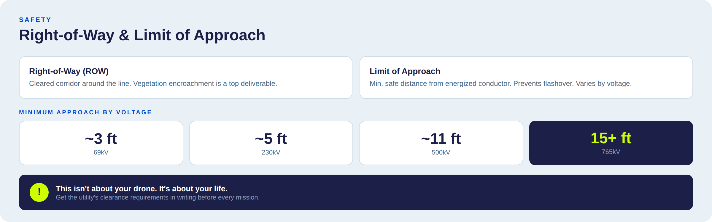
Two non-negotiables:
1. Right-of-Way (ROW): The cleared corridor around the transmission line. Vegetation encroachment documentation is one of the most commonly requested deliverables.
2. Limit of Approach: The minimum distance you and your drone must maintain from an energized conductor. Varies by voltage class. At 765kV, that's 15+ feet.
⚠️ Violating the limit of approach doesn't risk your drone. It risks your life. Confirm the voltage class and get the utility's clearance requirements in writing before every mission.
Why Transmission Towers Knowledge Matters Now
Three years ago, any DSP with a drone and a Part 107 could win utility work. That era is ending.
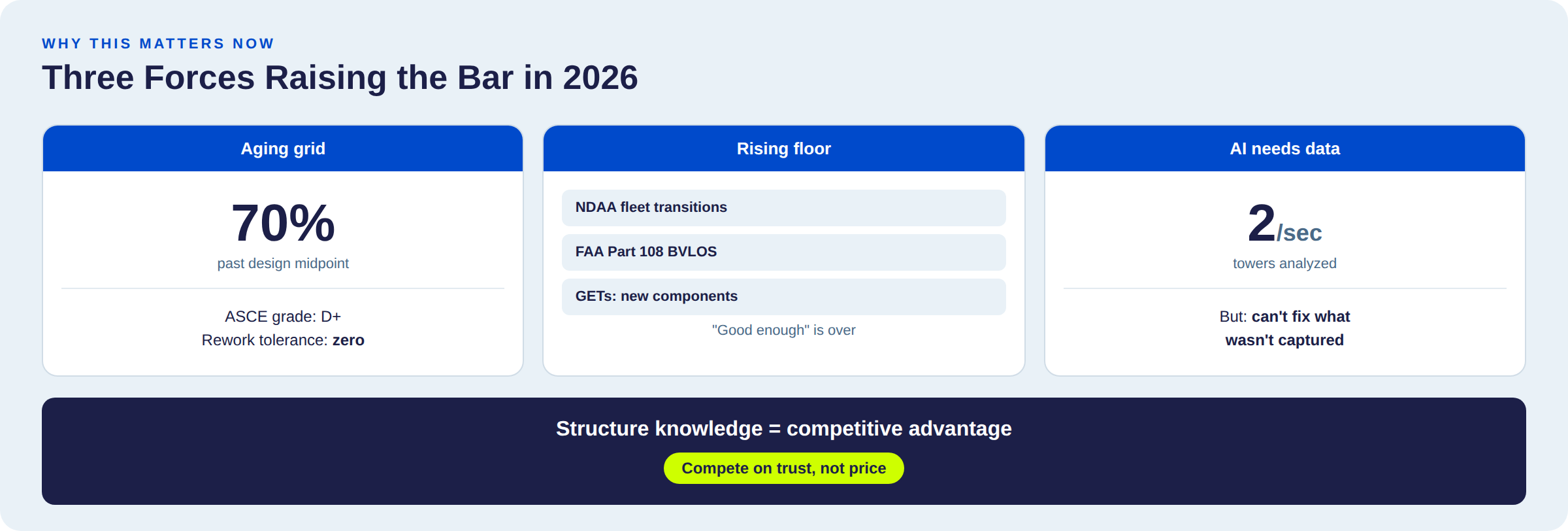
What's changed in 2026:
- Rework tolerance is gone. When 70% of transmission structures are past design life and the workforce is shrinking, utilities can't afford to wait weeks for data, find it incomplete, and send crews back. They want it right the first time.
- The regulatory floor is rising. NDAA compliance is forcing fleet transitions. FAA Part 108 is opening BVLOS corridors for transmission inspection. Grid-Enhancing Technologies are adding new components to existing structures. "Good enough" is no longer good enough.
- AI needs complete data to work. DetectOS analyzes two towers per second across transmission, distribution, and substation assets. But it needs complete, component-level imagery to work with. Skip the strain hardware on a dead-end tower, and no amount of post-processing saves the deliverable.
The Detect Data Quality Program was built to close this gap. The training video in this article is one module — covering structure identification, component awareness, and the domain expertise that turns every pilot on your team into your best pilot.
The DSP that captures utility-grade data from day one doesn't compete on price. They compete on trust.
Start Your Program Assessment →
Want to see what your current inspections are missing? Schedule a free asset analysis →
Detect is the operating system for utility-scale visual inspection — AI-powered defect detection, expert validation, same-day intelligence.
